2.3 Connections......................................................................................................................................... 102.4 Initial installation.................................................................................................................................. 112.5 TCP/IP parameters............................................................................................................................. 122.6 Firmware update ................................................................................................................................. 122.7 Factory reset........................................................................................................................................ 122.8 Connecting the digital inputs ............................................................................................................. 132.9 Connecting the digital outputs .......................................................................................................... 13
3 Application Scenarios ................................................................................................................................ 153.1 AnaGate I2C directly switched to an I2C device............................................................................ 153.2 AnaGate I2C and application board with integral power supply .................................................. 163.3 AnaGate I2C and application board with external power supply................................................. 17
4 Questions and Troubleshooting ............................................................................................................... 184.1 No LAN connection ............................................................................................................................ 184.2 No TCP/IP connection ....................................................................................................................... 184.3 No I2C communication....................................................................................................................... 194.4 Firewall ................................................................................................................................................. 19
ChartsChart 2-1: Example for connecting the digital inputs ............................................................................... 13Chart 2-2: Example for connecting the digital outputs ............................................................................. 14Chart 3-1: AnaGate I2C directly switched to an I2C device .................................................................... 15Chart 3-2: AnaGate I2C with an application board and integral power supply .................................... 16Chart 3-3: AnaGate I2C with an application board and external power supply ................................... 17
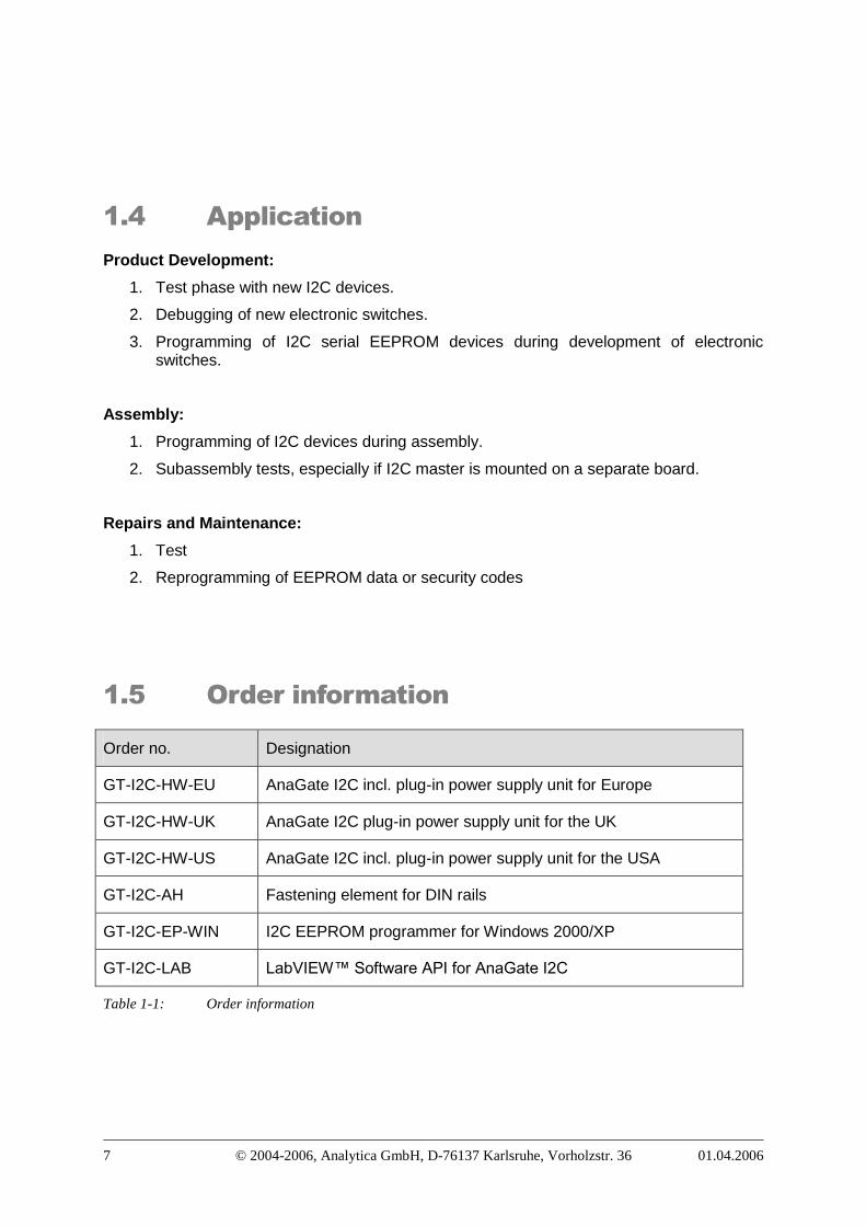
TablesTable 1-1: Order information .......................................................................................................................... 7Table 2-1: I2C jack assignment ................................................................................................................... 10Table 2-2: LAN jack assignment ................................................................................................................. 10Table 2-3: Digital inputs 1/2 ......................................................................................................................... 10Table 2-4: Digital inputs 3/4 ......................................................................................................................... 11Table 2-5: Digital output 1/2 ......................................................................................................................... 11Table 2-6: Digital output 3/4 ......................................................................................................................... 11
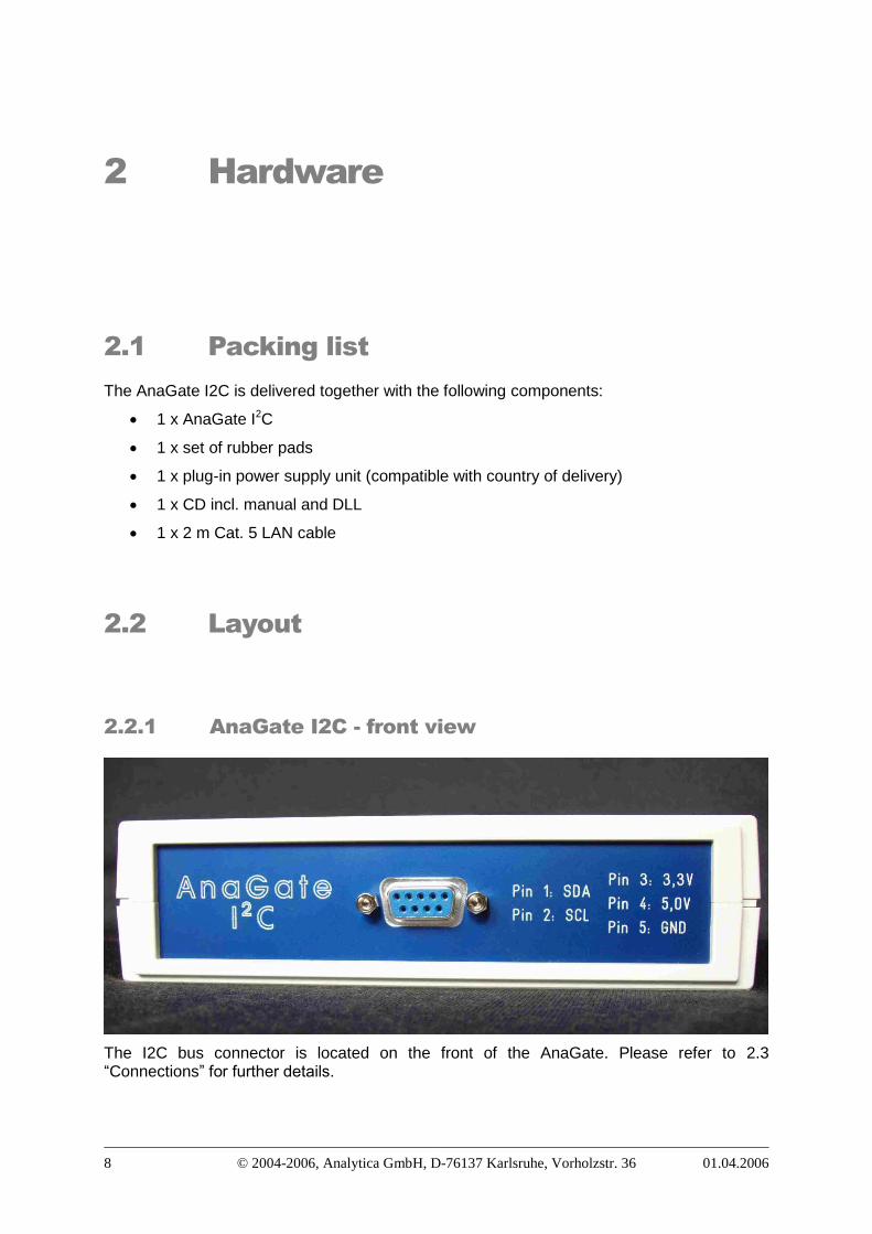
1.1 DescriptionThe AnaGate I2C connects a PC or other general device to a I2C bus via the TCP/IPnetwork protocol. The AnaGate I2C basically works as a I2C Master on the bus, whereby itcan be run in both single-master and multi-master modes. When being used in multi-mastermode, all the other masters on the bus must also be compatible with the multi-masteroperating mode.
1.2 FeaturesSupports I2C read and write commands for all I2C devices (both 7 and 10-bit format)
Variable I2C bus speed (100 or 400 kbps)
Separate plug for voltage supply
Supports 3.3 V and 5 V voltage to allow I2C devices to be operated on applicationboards
System is addressed using a proprietary TCP/IP protocol
Static or dynamic assignment (DHCP) of IP addresses
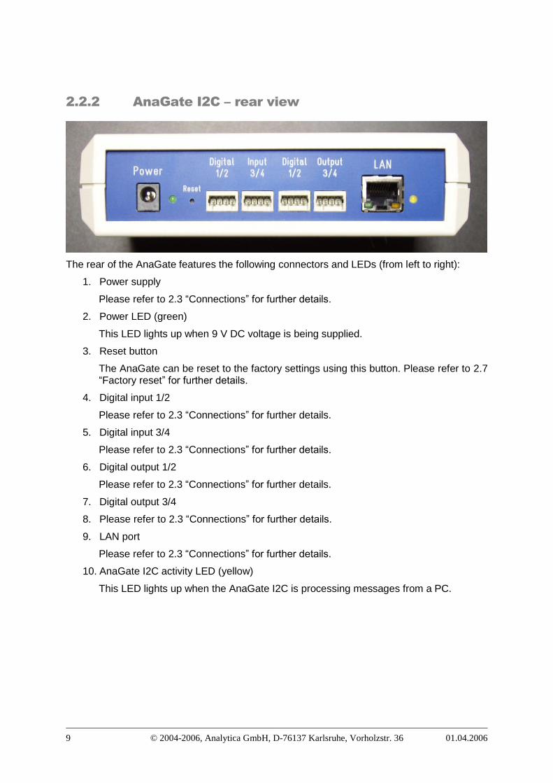
Die digital outputs 1 and 2 (galvanic decoupled) are fed out via a Wago clampingsocket The pins (arranged from left to right) are assigned as follows:
Pin Bedeutung1 Output 1 emitter of the opto coupler (npn)2 Output 1 collector of the opto coupler (npn)3 Output 2 emitter of the opto coupler (npn)4 Output 2 collector of the opto coupler (npn)
Table 2-5: Digital output 1/2
6. Digital output 3/4
Die digital outputs 3 and 4 (galvanic decoupled) are fed out via a Wago clampingsocket The pins (arranged from left to right) are assigned as follows:
Pin Bedeutung1 Output 1 emitter of the opto coupler (npn)2 Output 1 collector of the opto coupler (npn)3 Output 2 emitter of the opto coupler (npn)4 Output 2 collector of the opto coupler (npn)
Table 2-6: Digital output 3/4
7. Voltage supply
9V DC voltage is supplied using the accompanying power supply unit.
2.4 Initial installationPlease ensure that the AnaGate I2C is positioned on an even surface. Also keep it awayfrom direct sunlight.
Insert the round plug into the casing socket labelled 9V. Then plug the power supply unit intothe wall socket.
Insert the LAN cable into the plug labelled LAN and connect it either to a hub or switch, ordirectly to the PC using a crossover cable.
The AnaGate is delivered with the following settings:
Type of address: Static
IP address: 192.168.1.254
Network mask: 255.255.255.0
Gateway: 0.0.0.0
The AnaGate can now be configured using a standard browser (Internet Explorer, Mozilla,etc.) by using http://192.168.1.254.
2.5 TCP/IP parametersProceed as follows to configure the TCP/IP parameters:
1. Switching the dynamic/static IP address
Here you can switch between static IP and dynamic (via DHCP) addresses. If DHCPis being used, the remaining fields cannot be edited as this information is retrievedfrom the DHCP server. In this case, a DHCP server must be available and accessiblein the network.
2. IP address (not DHCP)
The IP address is entered in a.b.c.d format (e.g. 192.168.1.1) and is permanentlystored in the AnaGate.
3. Subnet mask (not DHCP)
The subnet mask is entered in a.b.c.d format (e.g. 255.255.255.0) and is permanentlystored in the AnaGate
4. Default gateway (not DHCP)
The default gateway is entered in a.b.c.d format (e.g. 192.168.1.200) and ispermanently stored in the AnaGate. Enter “0.0.0.0” if a default gateway is not required.
2.6 Firmware updatePlease visit our Web site http://www.anagate.de for further information.
2.7 Factory resetProceed as follows to restore the default factory settings (IP address/subnet mask:192.168.1.254/255.255.255.0):
1. Disconnect the AnaGate I2C from the power supply.
2. Press the reset button using a pointed instrument (do not release it).
3. Reconnect the power supply.
4. Release the reset button when the yellow AnaGate I2C activity LED lights up.
5. The device restarts and now operates again with the default factory settings.
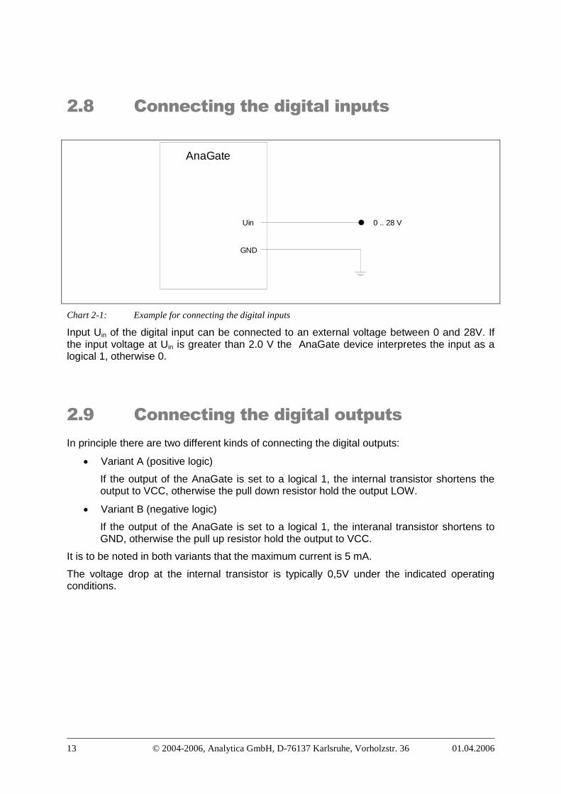
Chart 2-1: Example for connecting the digital inputs
Input Uin of the digital input can be connected to an external voltage between 0 and 28V. Ifthe input voltage at Uin is greater than 2.0 V the AnaGate device interpretes the input as alogical 1, otherwise 0.
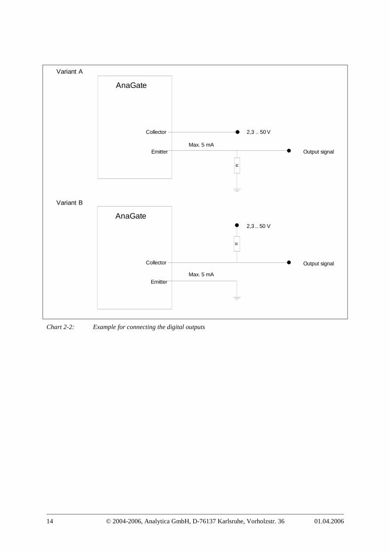
2.9 Connecting the digital outputsIn principle there are two different kinds of connecting the digital outputs:
Variant A (positive logic)
If the output of the AnaGate is set to a logical 1, the internal transistor shortens theoutput to VCC, otherwise the pull down resistor hold the output LOW.
Variant B (negative logic)
If the output of the AnaGate is set to a logical 1, the interanal transistor shortens toGND, otherwise the pull up resistor hold the output to VCC.
It is to be noted in both variants that the maximum current is 5 mA.
The voltage drop at the internal transistor is typically 0,5V under the indicated operatingconditions.
AnaGate I2C connected directly to an I2CDevice (power supplied by AnaGate I2C)
SCL
SDA
LAN
4,7k
4,7k
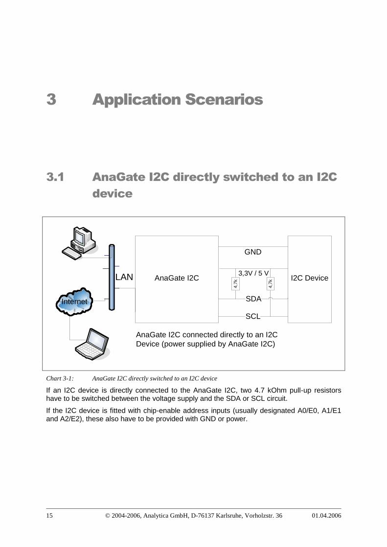
Chart 3-1: AnaGate I2C directly switched to an I2C device
If an I2C device is directly connected to the AnaGate I2C, two 4.7 kOhm pull-up resistorshave to be switched between the voltage supply and the SDA or SCL circuit.
If the I2C device is fitted with chip-enable address inputs (usually designated A0/E0, A1/E1and A2/E2), these also have to be provided with GND or power.
3.2 AnaGate I2C and application board withintegral power supply
Application Board
AnaGate I2C
SDA
SCL
I2CDevic
e
3,3V /5 V
GND
AnaGate I2C connected to an I2Cdevice located on an applicationboard powered by the AnaGateI2C (max. 200 mA).
µC(I2C
Master)
4,7k
4,7k
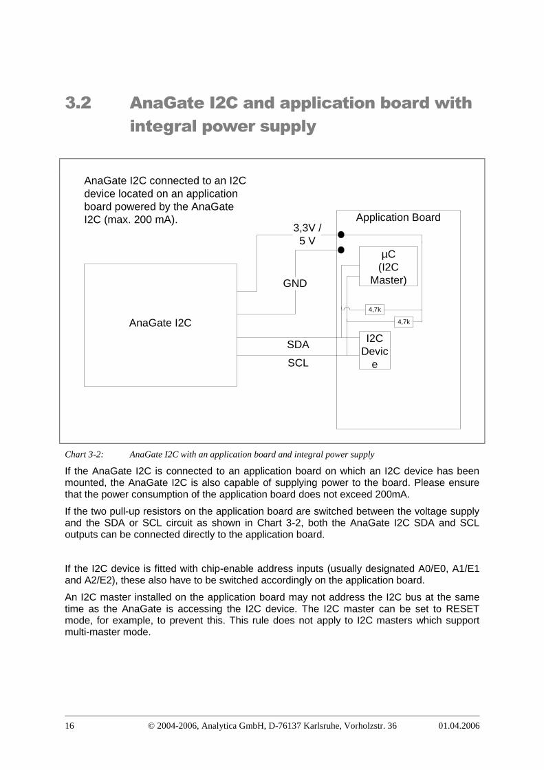
Chart 3-2: AnaGate I2C with an application board and integral power supply
If the AnaGate I2C is connected to an application board on which an I2C device has beenmounted, the AnaGate I2C is also capable of supplying power to the board. Please ensurethat the power consumption of the application board does not exceed 200mA.
If the two pull-up resistors on the application board are switched between the voltage supplyand the SDA or SCL circuit as shown in Chart 3-2, both the AnaGate I2C SDA and SCLoutputs can be connected directly to the application board.
If the I2C device is fitted with chip-enable address inputs (usually designated A0/E0, A1/E1and A2/E2), these also have to be switched accordingly on the application board.
An I2C master installed on the application board may not address the I2C bus at the sametime as the AnaGate is accessing the I2C device. The I2C master can be set to RESETmode, for example, to prevent this. This rule does not apply to I2C masters which supportmulti-master mode.
3.3 AnaGate I2C and application board withexternal power supply
Application Board
AnaGate I2C
SDA
SCL
I2CDevic
e
DC
5 VGND
GND
AnaGate I2C connected to an I2C device onan application board with external powersupply
µC(I2C
Master)
4,7k
4,7k
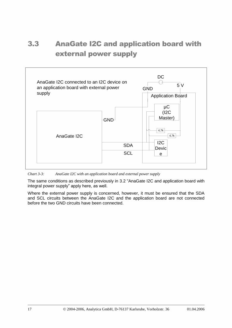
Chart 3-3: AnaGate I2C with an application board and external power supply
The same conditions as described previously in 3.2 “AnaGate I2C and application board withintegral power supply” apply here, as well.
Where the external power supply is concerned, however, it must be ensured that the SDAand SCL circuits between the AnaGate I2C and the application board are not connectedbefore the two GND circuits have been connected.
4.1 No LAN connectionIf no LAN connection is registered (the link LED next to the RJ45 socket does not light up),please check the wiring between the AnaGate I2C and the hub or switch. You need acrossover cable to connect the device to a PC.
Check that the AnaGate I2C is connected to the power supply.
4.2 No TCP/IP connectionIf you cannot set up a TCP/IP connection to the AnaGate, please proceed as follows:
1. Check for an existing LAN connection (see also 4.1).
2. Check if you can address the device with a ping.
To do this, open the MS Windows command prompt and enter the command “ping a.b.c.d” (replace a.b.c.d with the IP address of the AnaGate). If there is no response, check whether the RX LED next to the RJ45 socket lights up while executing the pingcommand.
If you still cannot address the device, perform a factory reset (see 2.7 for details),configure your PC using the IP address 192.168.1.253/255.255.255.0, and repeat theaforementioned procedure using the IP address 192.168.1.254.
3. Check whether you can open a TCP connection at port 5000.
To do this, open the MS Windows command prompt and enter the command “telnet a.b.c.d 5000” (replace a.b.c.d with the IP address of the AnaGate). If you do not get aconnection immediately check whether there is a firewall or packet filter installedbetween your PC and the AnaGate.