Concrete air permeability “in situ”test: status quo Luis Ebensperger*, Roberto Torrent** 1 Medición “in situ” de la permeabilidad al aire del hormigón: status quo * Consultor en Hormigón y sus Componentes, Buin. CHILE ** Materials Advanced Services SRL, Buenos Aires. ARGENTINA Resumen Los autores han estado involucrados en la creación y primeros ensayos y desarrollos del llamado “Método Torrent” para medir la permeabilidad al aire del hormigón. Transcurridos más de 15 años de ese trabajo fundacional, el artículo presenta una revisión de la evolución y estado de situación del método, incluido como Norma Oficial Suiza en 2003. Se presentan ejemplos de su aplicación en laboratorio y en obras (puentes, túneles, etc.), con datos de valores medidos, provenientes de distintos países del mundo. Se presentan correlaciones entre el coeficiente de permeabilidad al aire kT y otros indicadores de durabilidad, tales como la migración de cloruros (ASTM C1202) y la penetración de agua a presión (EN 12390-8) o por capilaridad. Finalmente se discuten sus perspectivas de uso futuro, como herramienta de control de calidad de estructuras nuevas, con las importantes implicancias que ello acarreará, así como de diagnóstico de estructuras existentes. Palabras Clave: Hormigón, método Torrent, permeabilidad Abstract The authors have been involved in the creation, preliminary tests and development of the “Torrent Method”, which is intended to test air permeability in concrete. It’s been more than 15 years since such foundational research and, now, this paper presents a review of the evolution and current situation of the Method, included in the Switzerland standards in 2003. Application examples conducted in laboratory and civil works (bridges, tunnels, and so on) are introduced, including data from different countries worldwide. Correlations between the air permeability coefficient kT and other durability indicators, such as chloride migration (ASTM C1202), penetration of water under pressure (EN 12390-8) or capillary action are presented. Finally the future prospective uses are discussed, as quality control tool for new structures, considering relevant implications they would lead to, as well as the diagnosis on existing structures. Keywords: Concrete, Torrent method, permeability Revista Ingeniería de Construcción Vol. 25 N o 3, Diciembre de 2010 www.ing.puc.cl/ric 371 1 Autor de correspondencia / Corresponding author: E-mail: [email protected]1. Introducción 1. Introduction Los problemas de durabilidad - más frecuentes de lo que sería deseable - que se encuentran en estructuras de hormigón, asociados principalmente a la depasivación y corrosión de las armaduras, al ataque químico (p.ej. por sulfatos) y a los ciclos de congelación y deshielo, han puesto en tela de juicio los enfoques tradicionales para la especificación y control de las estructuras de hormigón. En tanto que la capacidad portante de un elemento estructural es la resultante de su comportamiento integral, su durabilidad frente a acciones agresivas del medio ambiente depende básicamente del desempeño protector de una capa superficial relativamente delgada (20-50 mm), como se ilustra en la Figura 1. The more frequent than expected durability problems found in concrete structures, mainly due to reinforcement depassivation and corrosion, chemical attack (e.g. sulfate attack), frost and thaw cycles, have questioned traditional approaches on specification and control of concrete structures. Whilst the bearing capacity of a structural element is the result of its integral behavior, its durability against aggressive environment conditions basically depends on its protective cover performance, which is relatively thin (20-50 mm), as depicted in Figure 1. Fecha de recepción: 01/ 10/ 2010 Fecha de aceptación: 01/ 11/ 2010 PAG. 371 - 382 Medición “in situ” de la permeabilidad al aire del hormigón: status quo/Concrete air permeability “in situ”test: status quo
Transcript
Concrete air permeability “in situ”test: status quo
Luis Ebensperger*, Roberto Torrent**1
Medición “in situ” de la permeabilidad al aire del hormigón:status quo
* Consultor en Hormigón y sus Componentes, Buin. CHILE** Materials Advanced Services SRL, Buenos Aires. ARGENTINA
Resumen
Los autores han estado involucrados en la creación y primeros ensayos y desarrollos del llamado “Método Torrent” para medir la permeabilidad al aire del
hormigón. Transcurridos más de 15 años de ese trabajo fundacional, el artículo presenta una revisión de la evolución y estado de situación del método,
incluido como Norma Oficial Suiza en 2003. Se presentan ejemplos de su aplicación en laboratorio y en obras (puentes, túneles, etc.), con datos de valores
medidos, provenientes de distintos países del mundo. Se presentan correlaciones entre el coeficiente de permeabilidad al aire kT y otros indicadores de
durabilidad, tales como la migración de cloruros (ASTM C1202) y la penetración de agua a presión (EN 12390-8) o por capilaridad. Finalmente se discuten
sus perspectivas de uso futuro, como herramienta de control de calidad de estructuras nuevas, con las importantes implicancias que ello acarreará, así como
The authors have been involved in the creation, preliminary tests and development of the “Torrent Method”, which is intended to test air permeability in
concrete. It’s been more than 15 years since such foundational research and, now, this paper presents a review of the evolution and current situation of the
Method, included in the Switzerland standards in 2003. Application examples conducted in laboratory and civil works (bridges, tunnels, and so on) are
introduced, including data from different countries worldwide. Correlations between the air permeability coefficient kT and other durability indicators, such
as chloride migration (ASTM C1202), penetration of water under pressure (EN 12390-8) or capillary action are presented. Finally the future prospective uses
are discussed, as quality control tool for new structures, considering relevant implications they would lead to, as well as the diagnosis on existing structures.
Keywords: Concrete, Torrent method, permeability
Revista Ingeniería de Construcción Vol. 25 No3, Diciembre de 2010 www.ing.puc.cl/ric 371
1 Autor de correspondencia / Corresponding author:
Los problemas de durabilidad - más frecuentesde lo que sería deseable - que se encuentran en estructurasde hormigón, asociados principalmente a la depasivacióny corrosión de las armaduras, al ataque químico (p.ej.por sulfatos) y a los ciclos de congelación y deshielo, hanpuesto en tela de juicio los enfoques tradicionales parala especificación y control de las estructuras de hormigón.
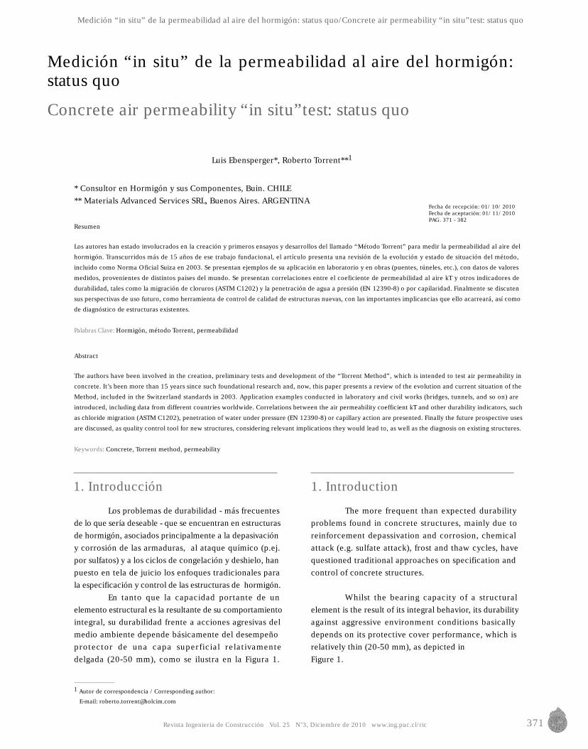
En tanto que la capacidad portante de unelemento estructural es la resultante de su comportamientointegral, su durabilidad frente a acciones agresivas delmedio ambiente depende básicamente del desempeñoprotector de una capa superficial relativamentedelgada (20-50 mm), como se ilustra en la Figura 1.
The more frequent than expected durabilityproblems found in concrete structures, mainly due toreinforcement depassivation and corrosion, chemicalattack (e.g. sulfate attack), frost and thaw cycles, havequestioned traditional approaches on specification andcontrol of concrete structures.
Whilst the bearing capacity of a structuralelement is the result of its integral behavior, its durabilityagainst aggressive environment conditions basicallydepends on its protective cover performance, which isrelatively thin (20-50 mm), as depicted inFigure 1.
Fecha de recepción: 01/ 10/ 2010Fecha de aceptación: 01/ 11/ 2010PAG. 371 - 382
Medición “in situ” de la permeabilidad al aire del hormigón: status quo/Concrete air permeability “in situ”test: status quo
372 Revista Ingeniería de Construcción Vol. 25 No3, Diciembre de 2010 www.ing.puc.cl/ric
Luis Ebensperger, Roberto Torrent
Figura 1. Concepto de Hormigón Superficial (Recubrimiento)Figure 1. Surface Concrete Concept (Coating)
Esta capa de recubrimiento debe proteger a las armadurascontra la corrosión inducida por la carbonatación o poringreso de cloruros, y es también la más afectada porataques químicos, congelación, etc. Lamentablemente,por ser la zona de más difícil compactación o por recibirlas tareas de acabado y por ser la más expuesta a lasconsecuencias del mal hábito de no curar las estructuras,esta vital capa superficial suele ser la de peor calidad enel elemento estructural.
Los criterios clásicos de especificación y controldel hormigón endurecido se basan casi exclusivamenteen resultados de ensayos de probetas moldeadas y,especialmente en el caso de la durabilidad, en fijar límitesmáximos a la relación agua/cemento.
Está claro porqué ese enfoque ha fracasado engarantizar la durabilidad: los resultados de las probetasmoldeadas nunca pueden representar la calidad de lacapa superficial, porque se preparan y curan de unamanera totalmente diferente a las condiciones reales enla estructura. Por otro lado, la relación agua/cemento esde difícil verificación en la práctica y últimamente hasido cuestionada como indicador de durabilidad.
Así, la calidad real de esa capa vital es ignoradalo que explica, en gran medida, el desempeñoinsatisfactorio de muchas estructuras, desde el punto devista de su durabilidad. La noción del hormigón derecubrimiento, que posee composición y propiedadesdiferentes a las del que se encuentra en el núcleo de lasestructuras data de los años ‘80 (Kreijger,1986; Newman,
This cover layer must protect reinforcement againstcorrosion induced by carbonation or chlorides and isalso the most affected by chemical attacks, frost damage,etc. Unfortunately it is the most affected by badcompaction, finishing and curing practices. Therefore,such essential surface layer turns out to be the one ofpoorest quality in the whole structural element.
The classic hardened concrete specificationsand control criteria are almost exclusively based onresults from cast test specimens and, specially as far asdurability is concerned, by establishing maximum limitsto the water/cement ratio.
It is now clear why this approach has failed inguaranteeing durability: the results of fast test specimenscould never represent the surface layer quality, becausethose are prepared and cured in a very different wayfrom the structure actual conditions. On the other hand,the water/cement ratio is hard to verify in practice and,laters, it has been questioned as a durability indicator.
So, the actual quality of such essential layer isignored, which explains to a great extent the unsatisfactoryperformance of several structures, from a durability pointof view. The basic knowledge that cover concrete, havingdifferent properties than those in the center of thestructure, goes back to the 80’s (Kreijger, 1986; Newman,
CO2 Cl- SO42-, Abrasió
Acero
Debido a:
• Segregación• Compactación• Curado
• Exudación• Acabado
• Microfisuras
CO2 Cl- SO42-, AbrasióCO2 Cl- SO42-, Abrasión/Abrasion, Hielo/Steel
Las probetas moldeadas y curadas enforma normalizada, NO representan lavital calidad del ‘recubrimiento’Specimens shaped and cured accordingto standard processes. Do not representthe essential quality of coating.
Revista Ingeniería de Construcción Vol. 25 No3, Diciembre de 2010 www.ing.puc.cl/ric 373
1987; Meyer, 1987) y fue incorporada al Código Modelo(CEB-FIP,1990), que expresaba en 1990 (traducción delinglés):
"No existe un método de aceptación generalpara caracterizar la estructura de poros del hormigón yrelacionarla con su durabilidad. Sin embargo, diversasinvestigaciones han indicado que la permeabilidad delhormigón, al aire o al agua, es una excelente medida desu resistencia al ingreso de medios agresivos en el estadogaseoso o líquido y así constituye una medida de ladurabilidad potencial de un hormigón dado."
"Actualmente no existen métodos de aceptacióngeneral para una determinación rápida de la permeabilidaddel hormigón ni de valores límites de la permeabilidaddel hormigón expuesto a diversas condiciones ambientales.Sin embargo es probable que se disponga de tales métodosen el futuro, lo que permitirá clasificar al hormigón enbase a su permeabilidad. Entonces podrán postularserequisitos para la permeabilidad del hormigón; ellosdependerán de las condiciones de exposición a que estésometida la estructura."
"Aunque el hormigón de mayor resistencia seráen la mayoría de los casos más durable que el hormigónde menor resistencia, la resistencia a compresión 'per se'no es una medida completa de la durabilidad, porqueésta depende principalmente de las propiedades de lascapas superficiales de un elemento de hormigón, las queejercen sólo una influencia limitada sobre la resistenciaa compresión."
La calidad del recubrimiento es el resultado,por un lado, de la dosificación de la mezcla elegida y,por el otro, del cuidado con el que el hormigón ha sidoprocesado (colocado, compactado, acabado, curado,etc.). Resulta obvio entonces que los ensayos sobreprobetas moldeadas, que son procesadas de una maneracompletamente diferente a los elementos estructurales,no darán jamás una imagen realista y representativa dela calidad real del recubrimiento. Por lo tanto, la únicaposibilidad es medirla directamente en la estructura,preferentemente "in situ" con métodos no-destructivos osino sobre testigos extraídos de ella.
El llamado “Método Torrent” para medir, demodo enteramente no-destructivo, la permeabilidad alaire del recubrimiento apunta exactamente a eso: aespecificar y controlar la calidad del recubrimiento de laestructura terminada.
Transcurridos unos 18 años de su creación, elartículo presenta una revisión de la evolución y estadode situación del método, incluido como Norma OficialSuiza en 2003.
1987; Meyer 1987) and was included by the Model Code(CEB-FIB, 1990), which in 1990 quoted:
“There is no generally accepted method tocharacterize the pore structure of concrete and to relateit to its durability. However, several experimentalinvestigations have indicated that concrete permeabilityboth with respect to air and to water is an excellentmeasure for the resistance of concrete against the ingressof aggressive media in the gaseous or in the liquid satetand thus is a measure of the potential durability of aparticular concrete."
“There are at present no generally acceptedmethods for a rapid determination of concrete permeabilityand of limiting values for the permeability of concreteexposed to different environmental conditions. However,it is likely that such methods will become available inthe future allowing the classification of concrete on thebasis of its permeability. Requirements for concretepermeability may then be postulated; they would dependon exposure classes i.e. environmental conditions towhich the structure is exponsed."
“Though concrete of a high strenght class is inmost instances more durable than concrete of a lowerstrenght class, compressive strength per se is not acomplete measure of concrete durability, becausedurability primarily depends on the properties of thesurface layers of a concrete member which have only alimited effect on concrete compressive strength.”
The quality of cover concrete is the result, onone hand, of the chosen mix design and, on the otherhand, the care applied during concrete processing(placement, compaction, finishing, curing, etc.) Then, itis obvious that cast test specimens, processed under verydifferent conditions from those in structural elements,would never provide a real and representative picture ofthe cover concrete real quality. Therefore, the onlypossibility is to measure it directly on the structure,preferably “in situ” by using non-destructive methods oron cover drilled from it.
The so called “Torrent Method” employed tomeasure cover concrete air permeability, in a completelynon-destructive way, aims directly to it: to specify andcontrol the cover concrete quality in a finished structure.
18 years from its creation, this paper presentsa review on shows the method’s evolution and currentsituation, included as a Switzerland Standard Method in2003.
Medición “in situ” de la permeabilidad al aire del hormigón: status quo/Concrete air permeability “in situ”test: status quo
374 Revista Ingeniería de Construcción Vol. 25 No3, Diciembre de 2010 www.ing.puc.cl/ric
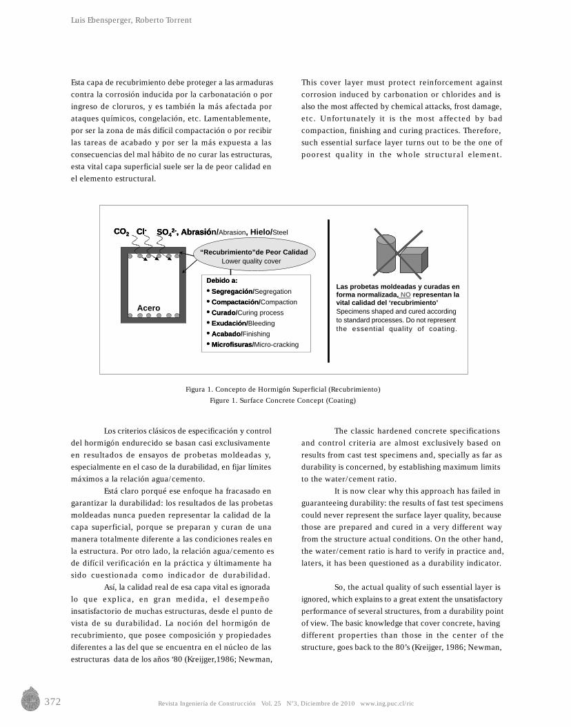
Figura 2. Esquema y detalles del Método TorrentFigure 2. Scheme and Details of Torrent Method
I: Internal chamber
E: external chamber
Pressure gauge (Pe = Pi)
Two chamber cell
Soft ring
Concrete
Luis Ebensperger, Roberto Torrent
2. Descripción del “método torrent”
La disposición del instrumental del aparato seesquematiza en la Figura 2. Sus dos característicasdistintivas son:
a) una celda con doble cámara, basada en el principiodel anillo de guarda. Consiste en una cámara internai y una cámara externa e.
b) un regulador de presión a membrana, cuya funciónes mantener a ambas cámaras siempre a la mismapresión (Pi = Pe).
La operación del aparato es como sigue: con laválvula 1 cerrada y la 2 abierta, se crea vacío en ambascámaras mediante la bomba. Cuando la presión Pi bajaa 30 mbar se cierra la válvula 2, momento a partir delcual la bomba solo puede actuar (cuando se lo permiteel regulador) sobre la cámara externa, de manera deequilibrar en todo momento la presión en ambas cámaras.De este modo, todo exceso de aire que ingrese lateralmenteen la cámara externa será evacuado por la cámara exterior.Así se logra que el flujo de aire hacia la cámara centralsea básicamente unidireccional (ver líneas de flujo en laFigura 2) y no afectado por el ingreso espurio de aire, seapor un deficiente sellado de la cámara externa o a travésde la más permeable 'piel' superficial.
2. “Torrent method” description
The layout of the device is sketched inFigure 2. Its two distinctive characteristics are:
a) A double-chamber cell, based on the guard-ringprinciple. It consists of an internal camber i and anexternal chamber e.
b) A membrane pressure regulator, which function isto always keep both chambers at the same pressure(Pi = Pe).
This device operates as follows: valves 1 isclosed and valve 2 is opened creating a vacuum insideboth chambers by means of vacuum pump. When pressurePi drops to 30 mbar then valve 2 closes, from thismoment the pump can only work (when the regulatorallows it) on the external chamber, so as to equilibrateat any moment the pressure in both chambers. In thisway the excess of air indirectly entering the externalchamber will be evacuated by the external chamber.Thus, a basically unidirectional air flow into the centralchamber is achieved (see flow lines in Figure 2), and notaffected by the ingress of spurious air because of adeficient sealing of the external chamber or through themost permeable surface “skin”.
1
Bomba de Vacío
Regulador(Pe=Pi)
PiPe
i
Celda
Computadora
Hormigón
Vá
e
Válvula/Valve 1
Bomba de Vacío/Vacuum pump
Regulador de Presión(Pe=Pi)
PiPe
i
i : Cámara interior
e : Cámara exterior
de 2 Cámaras
Computadora Táctil
Hormigón
Anillos blandos
lvula/Valve 2
e
Touchscreen computer
Regulador de PresiónPressure Regulator
Revista Ingeniería de Construcción Vol. 25 No3, Diciembre de 2010 www.ing.puc.cl/ric 375
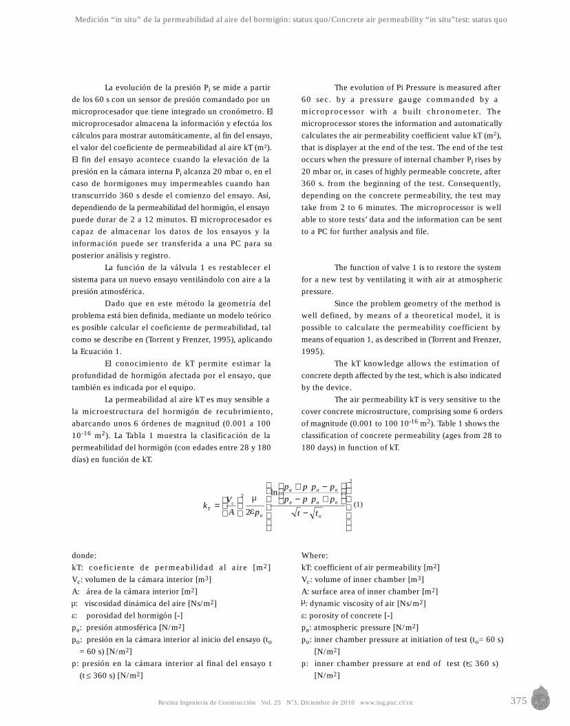
La evolución de la presión Pi se mide a partirde los 60 s con un sensor de presión comandado por unmicroprocesador que tiene integrado un cronómetro. Elmicroprocesador almacena la información y efectúa loscálculos para mostrar automáticamente, al fin del ensayo,el valor del coeficiente de permeabilidad al aire kT (m²).El fin del ensayo acontece cuando la elevación de lapresión en la cámara interna Pi alcanza 20 mbar o, en elcaso de hormigones muy impermeables cuando hantranscurrido 360 s desde el comienzo del ensayo. Así,dependiendo de la permeabilidad del hormigón, el ensayopuede durar de 2 a 12 minutos. El microprocesador escapaz de almacenar los datos de los ensayos y lainformación puede ser transferida a una PC para suposterior análisis y registro.
La función de la válvula 1 es restablecer elsistema para un nuevo ensayo ventilándolo con aire a lapresión atmosférica.
Dado que en este método la geometría delproblema está bien definida, mediante un modelo teóricoes posible calcular el coeficiente de permeabilidad, talcomo se describe en (Torrent y Frenzer, 1995), aplicandola Ecuación 1.
El conocimiento de kT permite estimar laprofundidad de hormigón afectada por el ensayo, quetambién es indicada por el equipo.
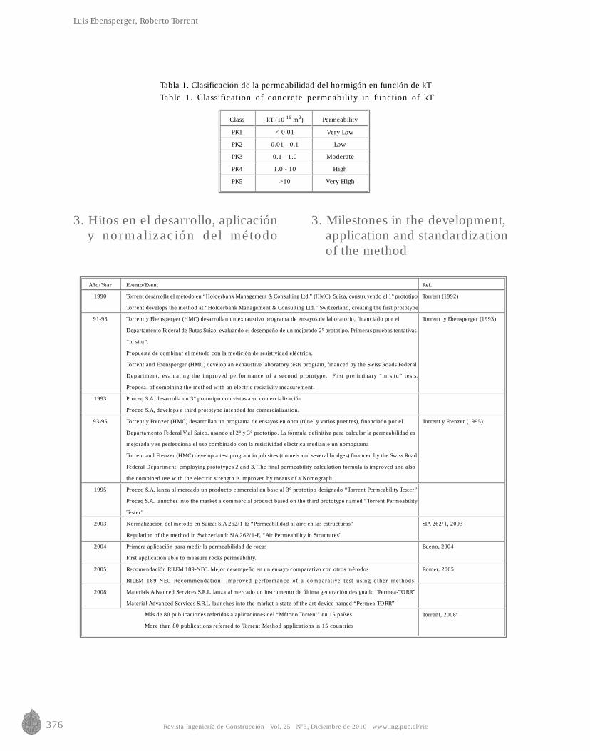
La permeabilidad al aire kT es muy sensible ala microestructura del hormigón de recubrimiento,abarcando unos 6 órdenes de magnitud (0.001 a 10010-16 m2). La Tabla 1 muestra la clasificación de lapermeabilidad del hormigón (con edades entre 28 y 180días) en función de kT.
donde:kT: coeficiente de permeabilidad al aire [m2]Vc: volumen de la cámara interior [m3]A: área de la cámara interior [m2]: viscosidad dinámica del aire [Ns/m2]: porosidad del hormigón [-]
pa: presión atmosférica [N/m2]po: presión en la cámara interior al inicio del ensayo (to
= 60 s) [N/m2]p: presión en la cámara interior al final del ensayo t
(t 360 s) [N/m2]
The evolution of Pi Pressure is measured after60 sec. by a pressure gauge commanded by amicroprocessor with a built chronometer. Themicroprocessor stores the information and automaticallycalculates the air permeability coefficient value kT (m2),that is displayer at the end of the test. The end of the testoccurs when the pressure of internal chamber Pi rises by20 mbar or, in cases of highly permeable concrete, after360 s. from the beginning of the test. Consequently,depending on the concrete permeability, the test maytake from 2 to 6 minutes. The microprocessor is wellable to store tests’ data and the information can be sentto a PC for further analysis and file.
The function of valve 1 is to restore the systemfor a new test by ventilating it with air at atmosphericpressure.
Since the problem geometry of the method iswell defined, by means of a theoretical model, it ispossible to calculate the permeability coefficient bymeans of equation 1, as described in (Torrent and Frenzer,1995).
The kT knowledge allows the estimation ofconcrete depth affected by the test, which is also indicatedby the device.
The air permeability kT is very sensitive to thecover concrete microstructure, comprising some 6 ordersof magnitude (0.001 to 100 10-16 m2). Table 1 shows theclassification of concrete permeability (ages from 28 to180 days) in function of kT.
Where:kT: coefficient of air permeability [m2]Vc: volume of inner chamber [m3]A: surface area of inner chamber [m2]: dynamic viscosity of air [Ns/m2]: porosity of concrete [-]
pa: atmospheric pressure [N/m2]po: inner chamber pressure at initiation of test (to= 60 s)
[N/m2]p: inner chamber pressure at end of test (t 360 s)
[N/m2]
Medición “in situ” de la permeabilidad al aire del hormigón: status quo/Concrete air permeability “in situ”test: status quo
(1)
2
2 ln
2
−
+−
−+
=
o
oa
oa
a
a
a
cT
tt
pppp
pppp
pAV
k
376 Revista Ingeniería de Construcción Vol. 25 No3, Diciembre de 2010 www.ing.puc.cl/ric
Tabla 1. Clasificación de la permeabilidad del hormigón en función de kTTable 1. Classification of concrete permeability in function of kT
Luis Ebensperger, Roberto Torrent
3. Hitos en el desarrollo, aplicacióny normalización del método
3. Milestones in the development,application and standardizationof the method
Class
PK1
PK2
PK3
PK4
PK5
kT (10-16 m2)
< 0.01
0.01 - 0.1
0.1 - 1.0
1.0 - 10
>10
Permeability
Very Low
Low
Moderate
High
Very High
Año/Year
1990
91-93
1993
93-95
1995
2003
2004
2005
2008
Ref.
Torrent (1992)
Torrent y Ebensperger (1993)
Torrent y Frenzer (1995)
SIA 262/1, 2003
Bueno, 2004
Romer, 2005
Torrent, 2008ªMás de 80 publicaciones referidas a aplicaciones del “Método Torrent” en 15 países
More than 80 publications referred to Torrent Method applications in 15 countries
Evento/Event
Torrent desarrolla el método en “Holderbank Management & Consulting Ltd.” (HMC), Suiza, construyendo el 1° prototipo
Torrent develops the method at “Holderbank Management & Consulting Ltd.” Switzerland, creating the first prototype
Torrent y Ebensperger (HMC) desarrollan un exhaustivo programa de ensayos de laboratorio, financiado por el
Departamento Federal de Rutas Suizo, evaluando el desempeño de un mejorado 2° prototipo. Primeras pruebas tentativas
“in situ”.
Propuesta de combinar el método con la medición de resistividad eléctrica.
Torrent and Ebensperger (HMC) develop an exhaustive laboratory tests program, financed by the Swiss Roads Federal
Department, evaluating the improved performance of a second prototype. First preliminary “in situ” tests.
Proposal of combining the method with an electric resistivity measurement.
Proceq S.A. desarrolla un 3° prototipo con vistas a su comercialización
Proceq S.A, develops a third prototype intended for comercialization.
Torrent y Frenzer (HMC) desarrollan un programa de ensayos en obra (túnel y varios puentes), financiado por el
Departamento Federal Vial Suizo, usando el 2° y 3° prototipo. La fórmula definitiva para calcular la permeabilidad es
mejorada y se perfecciona el uso combinado con la resistividad eléctrica mediante un nomograma
Torrent and Frenzer (HMC) develop a test program in job sites (tunnels and several bridges) financed by the Swiss Road
Federal Department, employing prototypes 2 and 3. The final permeability calculation formula is improved and also
the combined use with the electric strength is improved by means of a Nomograph.
Proceq S.A. lanza al mercado un producto comercial en base al 3° prototipo designado “Torrent Permeability Tester”
Proceq S.A. launches into the market a commercial product based on the third prototype named “Torrent Permeability
Tester”
Normalización del método en Suiza: SIA 262/1-E: “Permeabilidad al aire en las estructuras”
Regulation of the method in Switzerland: SIA 262/1-E, “Air Permeability in Structures”
Primera aplicación para medir la permeabilidad de rocas
First application able to measure rocks permeability.
Recomendación RILEM 189-NEC. Mejor desempeño en un ensayo comparativo con otros métodos
RILEM 189-NEC Recommendation. Improved performance of a comparative test using other methods.
Materials Advanced Services S.R.L. lanza al mercado un instrumento de última generación designado “Permea-TORR”
Material Advanced Services S.R.L. launches into the market a state of the art device named “Permea-TORR”
377Revista Ingeniería de Construcción Vol. 25 No3, Diciembre de 2010 www.ing.puc.cl/ric
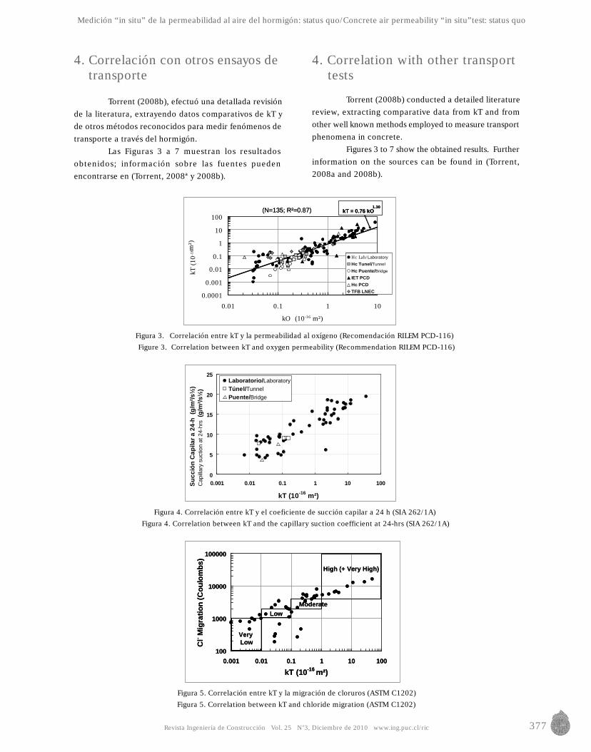
Figura 3. Correlación entre kT y la permeabilidad al oxígeno (Recomendación RILEM PCD-116)Figure 3. Correlation between kT and oxygen permeability (Recommendation RILEM PCD-116)
Figura 4. Correlación entre kT y el coeficiente de succión capilar a 24 h (SIA 262/1A)Figura 4. Correlation between kT and the capillary suction coefficient at 24-hrs (SIA 262/1A)
Figura 5. Correlación entre kT y la migración de cloruros (ASTM C1202)Figura 5. Correlation between kT and chloride migration (ASTM C1202)
Medición “in situ” de la permeabilidad al aire del hormigón: status quo/Concrete air permeability “in situ”test: status quo
4. Correlación con otros ensayos detransporte
Torrent (2008b), efectuó una detallada revisiónde la literatura, extrayendo datos comparativos de kT yde otros métodos reconocidos para medir fenómenos detransporte a través del hormigón.
Las Figuras 3 a 7 muestran los resultadosobtenidos; información sobre las fuentes puedenencontrarse en (Torrent, 2008ª y 2008b).
4. Correlation with other transporttests
Torrent (2008b) conducted a detailed literaturereview, extracting comparative data from kT and fromother well known methods employed to measure transportphenomena in concrete.
Figures 3 to 7 show the obtained results. Furtherinformation on the sources can be found in (Torrent,2008a and 2008b).
Hc LabHc TunelHc PuenteIET PCDHc PCDTFB LNEC
0.0001
0.001
0.01
0.1
1
10
100
0.01 0.1 1 10
kO (10-16 m²)
kT (1
0-16
m²)
Hc Lab/Laboratory
Hc Tunel/Tunnel
Hc Puente/Bridge
IET PCDHc PCDTFB LNEC
kT = 0.76 kO1.30
kT = 0.76 kO1.30
(N=135; R²=0.87)(N=135; R²=0.87)
Cap
illar
y su
ctio
n at
24-
hrs
(g/m
²/s½
)
0
5
10
15
20
25
0.001 0.01 0.1 1 10 100
kT (10-16 m²)
Su
cció
n C
apila
r a
24-h
(g
/m²/s
½)
Laboratorio/LaboratoryTúnel/TunnelPuente/Bridge
100
1000
10000
100000
0.001 0.01 0.1 1 10 100
kT (10-16 m²)
Cl- M
igra
tion
(Cou
lom
bs)
100
1000
10000
100000
0.001 0.01 0.1 1 10 100
kT (10-16 m²)
Cl- M
igra
tion
(Cou
lom
bs)
VeryLow
LowModerate
High (+ Very High)
VeryLow
LowModerate
High (+ Very High)
378 Revista Ingeniería de Construcción Vol. 25 No3, Diciembre de 2010 www.ing.puc.cl/ric
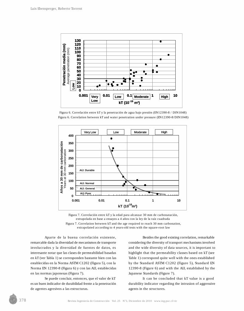
Figura 6. Correlación entre kT y la penetración de agua bajo presión (EN12390-8 / DIN1048)Figura 6. Correlation between kT and water penetration under pressure (EN12390-8/DIN1048)
Figura 7. Correlación entre kT y la edad para alcanzar 30 mm de carbonatación,extrapolada en base a ensayos a 4 años con la ley de la raíz cuadrada
Figura 7. Correlation between kT and the age required to reach 30 mm carbonation,extrapolated according to 4 years-old tests with the square-root law
Ave
rage
pen
etra
tion
(mm
)Y
ears
at 3
0 m
m c
arbo
natio
n
Luis Ebensperger, Roberto Torrent
Aparte de la buena correlación existente,remarcable dada la diversidad de mecanismos de transporteinvolucrados y la diversidad de fuentes de datos, esinteresante notar que las clases de permeabilidad basadasen kT (ver Tabla 1) se corresponden bastante bien con lasestablecidas en la Norma ASTM C1202 (Figura 5), con laNorma EN 12390-8 (Figura 6) y con las AIJ, establecidasen las normas japonesas (Figura 7).
Se puede concluir, entonces, que el valor de kTes un buen indicador de durabilidad frente a la penetraciónde agentes agresivos a las estructuras.
Besides the good existing correlation, remarkableconsidering the diversity of transport mechanisms involvedand the wide diversity of data sources, it is important tohighlight that the permeability classes based on kT (seeTable 1) correspond quite well with the ones establishedby the Standard ASTM C1202 (Figure 5), Standard EN12390-8 (Figure 6) and with the AIJ, established by theJapanese Standards (Figure 7).
It can be concluded that kT value is a gooddurability indicator regarding the intrusion of aggressiveagents in the structures.
Low Moderate HighVeryLow
Low
0102030405060708090
100110120130
0.001 0.01 0.1 1 10
kT (10 -16 m²)
Pen
etra
ción
med
ia (m
m)
Low Moderate HighVeryLow
Low
0102030405060708090
100110120130
0.001 0.01 0.1 1 10
kT (10
0102030405060708090
100110120130
0.001 0.01 0.1 1 10
kT (10 -16 m²)
Pen
etra
ción
med
ia (m
m)
0
50
100
150
200
250
300
350
400
0.001 0.01 0.1 1 10
kT (10 m²)
Añ
os
a 30
mm
de
carb
on
atac
ión
Very Low Low Moderate
-16
AIJ: Poor
AIJ: General
High
AIJ: Normal
AIJ: Durable
Very Low Low Moderate High
AIJ: Durable
379Revista Ingeniería de Construcción Vol. 25 No3, Diciembre de 2010 www.ing.puc.cl/ric
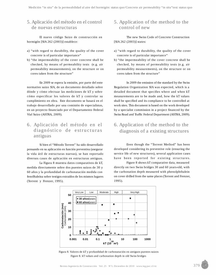
Figura 8. Valores de kT y profundidad de carbonatación en antiguos puentes suizosFigure 8. kT values and carbonation depth in old Swiss bridges
Car
bona
tion
(mm
)
Medición “in situ” de la permeabilidad al aire del hormigón: status quo/Concrete air permeability “in situ”test: status quo
5. Aplicación del método en el controlde nuevas estructuras
El nuevo código Suizo de construcción enhormigón [SIA 262 (2003)] establece:
a) “with regard to durability, the quality of the coverconcrete is of particular importance”
b) “the impermeability of the cover concrete shall bechecked, by means of permeability tests (e.g. airpermeability measurements), on the structure or oncores taken from the structure”
En 2009 se espera la emisión, por parte del entenormativo suizo SIA, de un documento detallado sobredónde y cómo efectuar las mediciones de kT y sobrecómo especificar los valores de kT y controlar sucumplimiento en obra. Este documento se basará en eltrabajo desarrollado por una comisión de especialistas,en un proyecto financiado por el Departamento FederalVial Suizo (ASTRA, 2009).
6. Aplicación del método en eldiagnóstico de estructurasantiguas
Si bien el “Método Torrent” ha sido desarrolladopensando en su aplicación en función preventiva (asegurarla vida útil de estructuras nuevas), se han reportadodiversos casos de aplicación en estructuras antiguas.
La Figura 8 muestra datos comparativos de kT,medida directamente sobre dos puentes suizos de 30 y60 años y la profundidad de carbonatación medida confenolftaleína sobre testigos extraídos de los mismos lugares(Torrent y Frenzer, 1995).
5. Application of the method to thecontrol of new
The new Swiss Code of Concrete Construction[SIA 262 (2003)] states:
a) “with regard to durability, the quality of the coverconcrete is of particular importance”
b) “the impermeability of the cover concrete shall bechecked, by means of permeability tests (e.g. airpermeability measurements), on the structure or oncores taken from the structure”
In 2009 the emission of the standard by the SwissRegulation Organization SIA was expected, which is adetailed document that specifies where and when kTmeasurements are to be made and, how the kT valuesshall be specified and its compliance to be controlled atwork sites. This document is based on the work developedby a specialist commission in a project financed by theSwiss Road and Traffic Federal Department (ASTRA, 2009).
6. Application of the method to thediagnosis of a existing structures
Even though the “Torrent Method” has beendeveloped considering its preventive role (ensuring theservice life of new structures), several application caseshave been reported for existing structures.
Figure 8 shows kT comparative data, measureddirectly on two Swiss bridges 30 and 60 years-old, withthe carbonation depth measured with phenolphthaleinon cover drilled from the same places (Torrent and Frenzer,1995).
0
10
20
30
40
50
0.001 0.01 0.1 1 10 100 1000kT (10 m²)
Car
bona
taci
ón (m
m)
30 años/years60 años/years
Very Low Low Moderate High Very High
-16
380 Revista Ingeniería de Construcción Vol. 25 No3, Diciembre de 2010 www.ing.puc.cl/ric
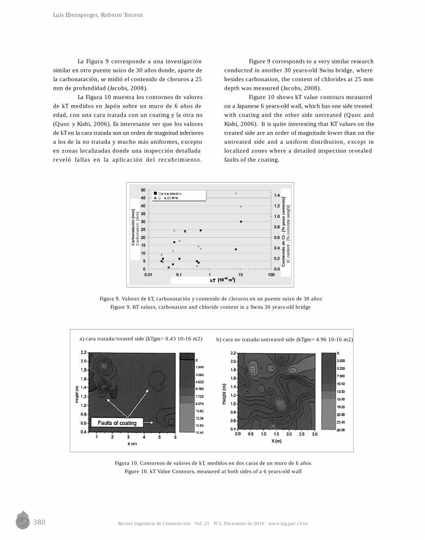
Figura 9. Valores de kT, carbonatación y contenido de cloruros en un puente suizo de 30 añosFigure 9. KT values, carbonation and chloride content in a Swiss 30 years-old bridge
Figura 10. Contornos de valores de kT, medidos en dos caras de un muro de 6 añosFigure 10. kT Value Contours, measured at both sides of a 6 years-old wall
Luis Ebensperger, Roberto Torrent
La Figura 9 corresponde a una investigaciónsimilar en otro puente suizo de 30 años donde, aparte dela carbonatación, se midió el contenido de cloruros a 25mm de profundidad (Jacobs, 2008).
La Figura 10 muestra los contornos de valoresde kT medidos en Japón sobre un muro de 6 años deedad, con una cara tratada con un coating y la otra no(Quoc y Kishi, 2006). Es interesante ver que los valoresde kT en la cara tratada son un orden de magnitud inferioresa los de la no tratada y mucho más uniformes, exceptoen zonas localizadas donde una inspección detalladareveló fallas en la aplicación del recubrimiento.
Figure 9 corresponds to a very similar researchconducted in another 30 years-old Swiss bridge, wherebesides carbonation, the content of chlorides at 25 mmdepth was measured (Jacobs, 2008).
Figure 10 shows kT value contours measuredon a Japanese 6 years-old wall, which has one side treatedwith coating and the other side untreated (Quoc andKishi, 2006). It is quite interesting that KT values on thetreated side are an order of magnitude lower than on theuntreated side and a uniform distribution, except inlocalized zones where a detailed inspection revealedfaults of the coating.
a) cara tratada/treated side (kTgm= 0.43 10-16 m2)
b) cara no tratada/untreated side (kTgm= 4.96 10-16 m2)
Car
bona
taci
ón [m
m]
Car
bona
tion
[mm
]
Con
teni
do d
e C
I - [%
pes
o ce
men
to]
IC c
onte
nt -
[% c
oncr
ete
wei
ght]
381Revista Ingeniería de Construcción Vol. 25 No3, Diciembre de 2010 www.ing.puc.cl/ric
Medición “in situ” de la permeabilidad al aire del hormigón: status quo/Concrete air permeability “in situ”test: status quo
7. Conclusiones
Este paseo por la evolución del “Método Torrent”y su situación actual permite extraer las siguientesconclusiones:• El método es adecuado para medir la resistencia del
hormigón de recubrimiento a la penetración, por distintosmecanismos, de agentes agresivos que afectan ladurabilidad de las estructuras
• Se correlaciona muy bien con otros métodos para medirfenómenos de transporte en el hormigón, con la ventajade ser más rápido y totalmente no destructivo
• Su introducción en las Normas Suizas SIA 262 y 262/1constituye un paso fundacional hacia el empleo deconceptos de desempeño para especificar y controlarla durabilidad de las estructuras, con las siguientesventajas:o Al controlar el producto terminado (la estructura “in
situ”), consolida una mentalidad orientada aldesempeño en todos los actores del procesoconstructivo (constructoras, hormigoneras, proveedoresde materiales, etc.)
o Tiende a erradicar malas prácticas (adiciónindiscriminada de agua al hormigón, insuficientecompactación, falta de curado, adición de agua y/ocemento en el acabado de pisos, etc.)
o Fomenta el uso de soluciones innovadoras, quemejoren la calidad del recubrimiento (membranaspermeables en los encofrados, “dewatering” por vacíode losas, uso de hormigones especiales, tales comoautocompactantes , de a l to desempeño,“autocurantes”, etc.)
• Constituye una herramienta útil en el diagnóstico delestado de estructuras antiguas, identificando las áreasmás vulnerables, donde profundizar otros estudios
• Algunas experiencias puntuales indican la posibilidadde usarlo sobre otros materiales porosos, tales comopiedras (conservación de monumentos) y tejas o baldosascerámicas.
7. Conclusions
This tour along the evolution and currentsituation of “Torrent Method” allow us to draw thefollowing conclusions:• The method is suitable to measure the resistance of the
concrete cover against the intrusion of aggressive agents(by diverse mechanisms) that affect structures durability.
•It correlates very well with other methods to measuretransport phenomena in concrete, having the advantageof being faster and completely non-destructive.
• Its inclusion in Swiss Standards SIA 262 and 262/1constitutes a foundational step towards the use ofperformance concepts to specify and control structuresdurability, with the following advantages:
o By controlling the finished product (the structure onsite), it consolidates a new mindset, performanceoriented, in all the parties involved in the constructionprocess (construction and concrete companies,material suppliers, etc).
o It tends to erradicate bad practices (uncontrolledwater addition to concrete, poor compaction, lackof curing, water or cement addition for floor finishing,etc).
o It stimulates the use of innovative solutions to improvethe quality of cover concrete (permeable membranesfor formworks, vacuum“dewatering” of slabs andthe use of special concretes, such as self-compacting,high performance or self-curing concretes, etc.)
• It constitutes a useful tool for the diagnosis of structuresconditions, by identifying the most vulnerable areaswhere other studies may be conducted.
• Some pioneering work indicates the possibility ofemploying this method on other porous materials, suchas stones (monument conservation), tiles or ceramictiles.
382 Revista Ingeniería de Construcción Vol. 25 No3, Diciembre de 2010 www.ing.puc.cl/ric
8. Referencias / References
Luis Ebensperger, Roberto Torrent
ASTRA (2009), ASTRA empfehlungen zur Qualitätskontrolle von Beton mit Luftpermeabilitätsmessungen, Office Fédéral desR o u t e s , V S S R e p o r t 6 4 1 , D e c e m b e r 2 0 0 9 , B e r n , S w i t z e r l a n d . D o w n l o a d a b l e f r o mhttp://partnershop.vss.ch/downloadAnhang.aspx?ID=8e2c2936-d3a4-43d7-8dd6-b0706e9a65fb&ID Sprache=1
Bueno V. (2004), “Estudio de Factibilidad de un Nuevo Ensayo de Permeabilidad en Rocas” (in Spanish), Univ. del Zulia, Maracaibo,Venezuela, Oct. 2004, 88 p.
CEB-FIP (1990), MODEL CODE 1990, Final Draft, Section d.5.3: "Classification by Durability", CEB Bulletin d'Information N°205, Lausanne, July 1991.
Jacobs F. (2008), “Beton zerstörungsfrei untersuchen“ (in German), der Bauingenieur, n.3, pp. 24-27.Kreijger P.C (1984), "The skin of concrete. Composition and properties", Mater. & Struct. 17(100) 275-283.Meyer A. (1987), "The importance of the surface layer for the durability of concrete structures", ACI SP-100, v.1, 49-61.Newman K. (1987), "Labcrete, realcrete and hypocrete. Where we can expect the next major durability problems", ACI SP-100,
v.2, 1259-1283.Quoc P.H.D. y Kishi T. (2006), “Measurement of air permeation property of cover concrete”, Proc. JSCE Annual Meeting, v. 61,
Disk 2, 2 p.Romer M. (2008), RILEM Recommendation TC 189-NEC "Comparative test - Part I - Comparative test of penetrability methods”,
Materials & Structures, v38, Dec 2005, pp. 895 – 906, updated in v41, Apr 2008, pp. 443-447.SIA 262 (2003), Swiss Standard: “Concrete Construction”, part of Swiss structural codes (German, French, Italian and English
versions available).SIA 262/1 (2003), Norme Suisse: "Construction en béton – Spécifications complémentaires", Annexe E: Perméabilité à l'air dans
les Structures, pp. 30-31 (in German and French)Torrent R. J. (1992), "A two-chamber vacuum cell for measuring the coefficient of air-permeability of the concrete cover on site",
Materials & Structures, v. 25, n.150, pp. 358-365.Torrent R. (2008a), “Non-destructive Site Air-Permeability Test – Annotated Bibliography”, Materials Advanced Services Ltd.,
Buenos Aires, October 2008. www.m-a-s.com.arTorrent R. (2008b), “Non-destructive Site Air-Permeability Test – Relation with other transport test methods”, Materials Advanced
Services Ltd., Buenos Aires, October 2008. www.m-a-s.com.arTorrent R. y Ebensperger L. (1993), “Studie über Methoden zur Messung und Beurteilung der Kennwerte des Überdeckungsbetons
auf der Baustelle” (in German), Office Fédéral des Routes, Rapport No. 506, Bern, Suiza, 119 p.Torrent R. y Frenzer G. (1995), "Methoden zur Messung und Beurteilung der Kennwerte des Ueberdeckungsbetons auf der
Baustelle", Report N° 516, Office Fédéral des Routes, Zürich.